


Transmitter Measurement Solution | Air Velocity Measurement for HVAC Ducts and Ventilation Systems
Transmitter Measurement Solution | Air Velocity Measurement for HVAC Ducts and Ventilation Systems
In ventilation and air conditioning
systems, ducts are responsible for delivering conditioned air to different
areas. Whether the actual air velocity inside the duct meets the design
requirements affects the operating performance of the supply air, return air,
and exhaust air systems. Whether in air handling units (AHUs), main ducts,
supply and return air ducts, or large ventilation systems, reliable measurement
data is required to understand airflow conditions and serve as the basis for
equipment adjustment, operation verification, and HVAC control.
However, airflow inside a duct is not
evenly distributed. If the measurement result only reflects the airflow
condition at a local position, it may not accurately represent the average air
velocity across the entire duct cross-section. Therefore, obtaining
representative measurement data is an important requirement for HVAC systems.
Localized Turbulence and Air Velocity Variations Increase the Difficulty of Duct Measurement
Airflow inside a duct is affected by duct
bends, dampers, fan outlets, and duct configurations, resulting in localized
turbulence and air velocity variations. Even within the same duct
cross-section, the measured air velocity may vary at different locations. If
only a single measurement point is used, the measurement result can easily be
influenced by the probe position and the local airflow field and may not
accurately represent the average airflow condition across the entire duct
cross-section.
When an HVAC system operates at low air
velocity or uses variable air volume (VAV) control, the dynamic pressure
generated by the airflow also decreases as the air velocity decreases, making
the differential pressure between total pressure and static pressure more
difficult to detect. Therefore, duct measurement requires not only suitable
differential pressure measurement equipment, but also a pressure sampling
method capable of obtaining pressure from different locations.
Establishing a Duct Measurement Solution with Multi-Port Averaging Pressure Sampling
To address the issue of uneven airflow
distribution inside ducts, an Average Flow Measuring Tube can be
combined with a Differential Pressure Transmitter to establish an
average air velocity measurement solution for duct applications. Compared with
single-point measurement, the multi-port pressure sampling structure acquires
pressure from different locations across the duct cross-section and averages
the differential pressure measured at each sampling point. This reduces the
influence of localized turbulence, uneven air velocity distribution, and
differences in probe position on the measurement results, allowing the measured
data to more accurately represent the average airflow condition inside the
duct.
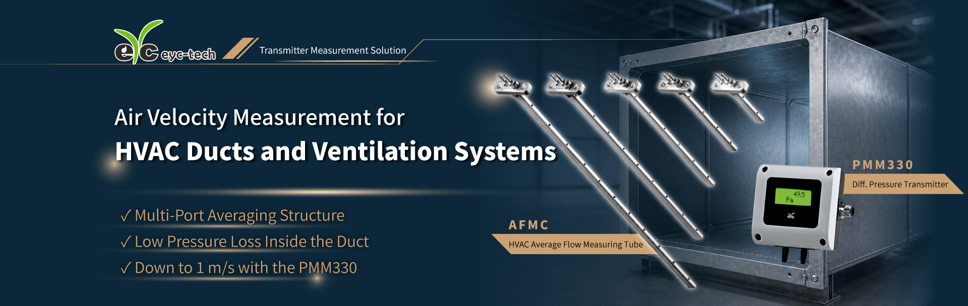
The eyc-tech AFMC HVAC Average Flow
Measuring Tube operates based on the Pitot tube measurement principle. It
separately measures the total pressure and static pressure of the airflow, uses
the difference between them to obtain the dynamic pressure, and then converts
it into the average air velocity. When volumetric flow measurement is required,
the volumetric flow rate can be further calculated based on the duct
cross-sectional area.
Combined with a Differential Pressure Transmitter for Low Air Velocity Measurement
For low air velocity duct applications, the eyc-tech PMM330 Differential Pressure Transmitter can be used. With an
appropriate measuring tube specification, installation conditions, and
differential pressure range configuration, it can support air velocity
measurement down to 1 m/s.
In this measurement solution, the Average
Flow Measuring Tube acquires the total pressure and static pressure, while
the Differential Pressure Transmitter measures the differential pressure
between them and converts it into the average air velocity inside the duct.
When the duct cross-sectional area is known, the average air velocity can also
be further converted into volumetric flow rate, providing data for supply and
exhaust air control, equipment adjustment, and operation verification.
During on-site installation, the measuring
tube is inserted into the duct. The AFMC HVAC Average Flow Measuring Tube is available in various measuring tube lengths from 100 ... 1000 mm,
allowing users to select the appropriate specification according to the duct
size and installation conditions, so that the multi-port pressure sampling
positions correspond to the airflow distribution across the duct cross-section.
During installation, the total pressure sensing ports should face the upstream
airflow direction, and locations near duct bends, dampers, fan outlets, and
significant duct size changes should be avoided as much as possible to reduce
the influence of localized turbulence on the measurement results.
Repeatability Verification Through Wind Tunnel Testing
To evaluate the measurement performance of
the product in HVAC duct applications, the measuring tube was tested using a
wind tunnel calibration system for repeatability testing and air velocity
up-and-down cycle testing.
In the repeatability test from 1 to 20
m/s, the results showed that the repeatability error gradually decreased as
the air velocity increased. Within the 10 to 20 m/s test range, the
measurement results demonstrated better consistency, covering the typical air
velocity range of HVAC main ducts and high-airflow supply and exhaust air
systems.
The air velocity up-and-down cycle test
simulated the change of airflow inside the duct from low to high air velocity
and then from high back to low air velocity. The test results showed that the
measurement curve accurately tracked the changes in the reference air velocity
and maintained a consistent trend throughout the three test cycles,
demonstrating the product's tracking capability and repeatable measurement
stability during air velocity changes.
Suitable for HVAC Duct Measurement Applications
This solution can be applied to air
handling units (AHUs), main ducts, supply air ducts, return air ducts, exhaust
air ducts, and large ventilation ducts to obtain the average air velocity
across the cross-section.
By selecting the appropriate measuring tube
length and differential pressure range according to the duct size, air velocity
range, and on-site installation conditions, an air velocity measurement
solution can be established to meet the requirements of different HVAC systems.
The measured average air velocity helps users understand the actual airflow
condition inside the duct. When volumetric flow data is required, it can also
be further calculated by combining the duct cross-sectional area, providing a database
for equipment control, operation verification, and system management.
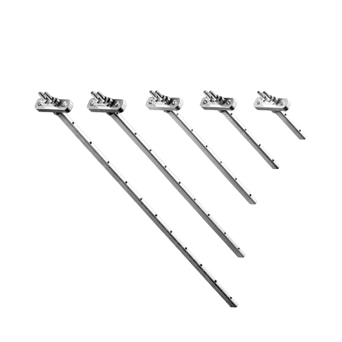
Features : Multi-hole averaging design for stable HVAC duct measurement down to 1 m/s with the PMM330.
Operating pressure : 1 bar
Operating temperature : 0 ... 80°C
Length : 100 ... 1000 mm

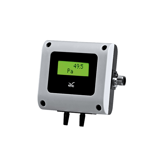
Feature : Suitable for HVAC and light industry
Measuring element : Hot-wire type diff. pressure sensor, flow-through
Measuring range : ±50 ... ±1500 Pa
Output : 4 ... 20 mA / 0 ... 10 V / RS-485
Accuracy : ±1.0% F.S. ±4% M.V
IP rating : IP65